When designing a structure which is to be hot dip galvanized, it must be borne in mind that articles are immersed into and withdrawn from a bath containing molten zinc heated to a temperature of 450ºC.
Design and fabrication is required to conform to acceptable standards which apply, regardless of whether a galvanized or a painted coating is to be applied. In the case of galvanizing, some additional requirements which aid access and drainage of molten zinc, will improve the quality of the coating and also reduce costs.
With certain fabrications, holes which are present for other purposes may fulfil the requirements of venting of air and draining of zinc; in other cases it may be necessary to provide extra holes for this purpose.
For complete protection, molten zinc must be able to flow freely over all surfaces of a fabrication. With hollow sections or where there are internal compartments, the galvanizing of the internal surfaces eliminates any danger of hidden corrosion occurring in service.
If the design of an article includes sealed hollow sections guidance on correct venting and drainage must be incorporated – click here for further advice
- a examples of holes in end plates
- b examples of crops and cut-outs in stiffeners
- c cut-outs in fabricated beams
- d holes in web of beams
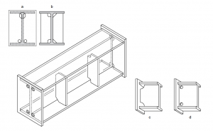
External stiffeners, welded gussets and webs on columns and beams and gussets in channel sections should have their corners cropped. The gaps created should be as large as possible without compromising structural strength. If welding is required around the edge created, a radiused corner is desirable, to facilitate continuity of the weld around the cut end to the other side. Circular holes are less effective; if used, they should be as close to corners and edges as practicable. Consultation with the galvanizer regarding the appropriate vent and drainage hole sizes is recommended.
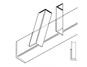
Angle bracings should, if possible, be stopped short of the main boom flange. This will allow the free flow of molten zinc across the surface of the flange, enhancing drainage from the structure. This will assist the development of a smoother galvanized coating, reduce the potential for retention of ash on the surface of the flange and help to avoid air traps within the structure, which could lead to uncoated areas.
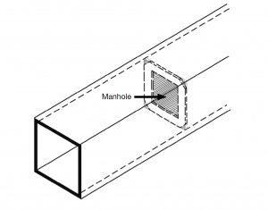
Internal diaphragms in large box sections should have cropped corners and a ‘manhole’. Internal diaphragms on small box sections should have cropped corners.
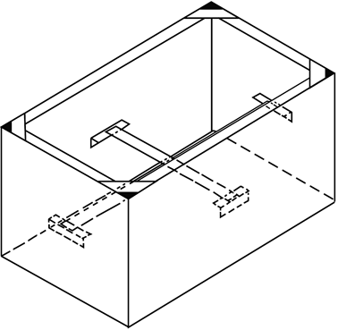
Large open top tanks should be stayed to minimise distortion. Where angles are used to rim the tank, appertures must be provided in the corners. Angles or flats used as stays should be as close as possible to the tank wall thickness.
Additional guidance for design of structural steelwork for hot dip galvanizing
In circumstances where, due to design restrictions, general design guidance (as set out above) cannot be followed and the introduction of holes or other fabrication features into the ‘K’ areas of a section (where the web and flange meet) is unavoidable, please consult GA to discuss how best to finalise the design of the fabrication.
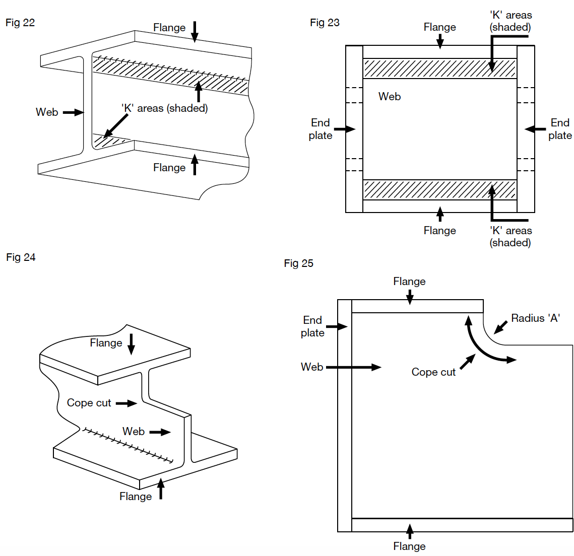
Cope cutting of beams is a common feature in modern steel construction. For optimum results during galvanizing, where flame-cut copes have been introduced into a fabrication, the following steps are recommended:
- Use a large radius for the cope – 20 mm minimum if possible.
- After cope cutting, grind off any hardened steel surface layer.
- Provide a smoothly ground cope cut surface avoiding notches, grooves and other surface irregularities.
- Chamfer the edges to the cope cut.
It is very important when considering design detailing of steelwork for hot dip galvanizing that considerations for correct venting and drainage of sealed hollow sections are taken into consideration.
This is part of the series HDG Literature and can be requested from Galvanizers Association in a pdf format. Read more about the Design for Galvanizing Wall Chart.
